This article was last updated on 2024-11-19, the content may be out of date.
0. Lab Document
1. Prove Ohm’s Law, KCL, and KVL in a Circuit
Circuit Schematic
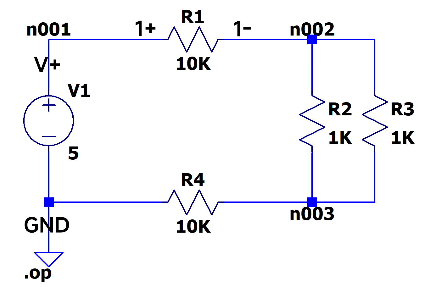
Proof of Concept - Omega Lab 01 - 1 - Schematic
Description
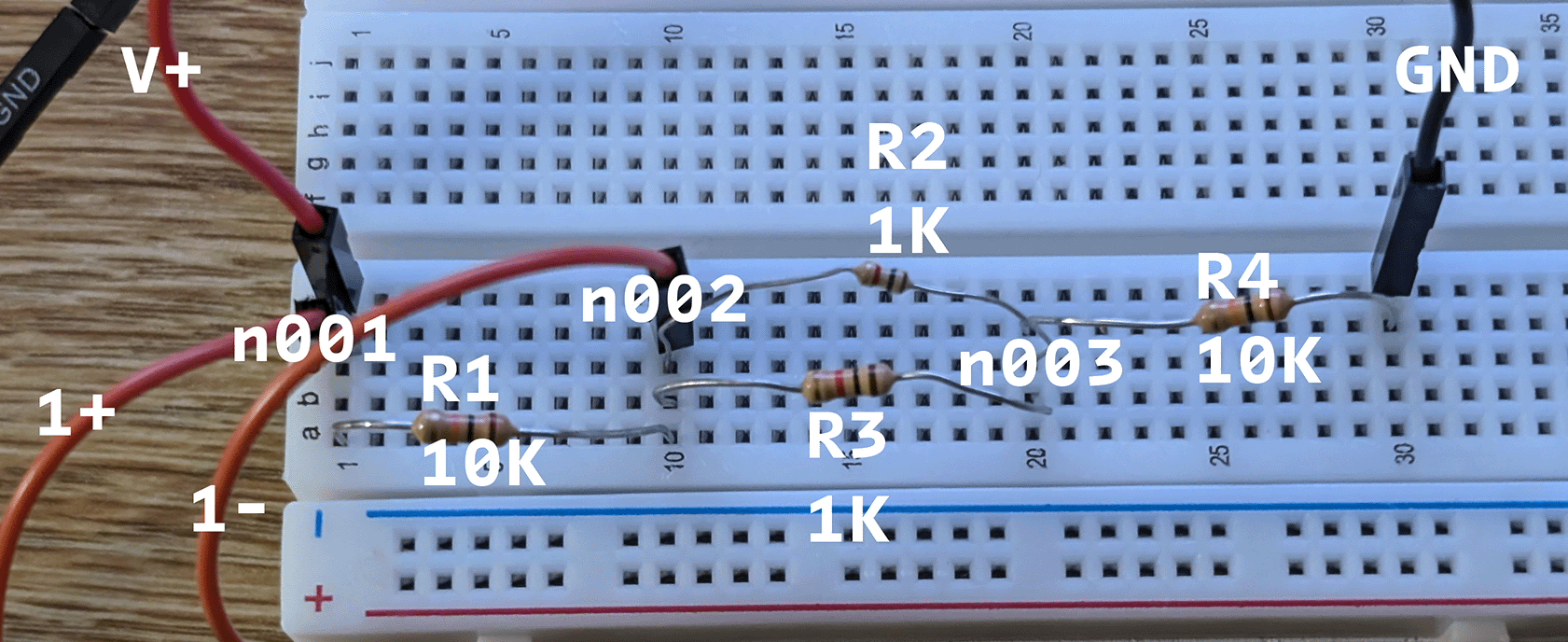
Based on the description of Ohm’s Law, the voltage is equal to current times resistance. So, I will check the real measurements with voltmeter and the theoretic values.
Based on the description of KCL, the current goes into a node is equal to current goes out the node. So I am going to measure the currents and add them together to check if it matches the theory.
Based on the description of KVL, the net voltage of nodes in the loop is equal to zero. So, I am going to measure all the voltage across the loop and check the sum.
Analysis
We know that, the Ohm’s Law, KCL, and KVL can be shown as these formulas:
Based on ∑Iin=∑Iout, we should see I(R1)=I(R2)+I(R3), since I(R1) is the current goes into node n002 and I(R2)+I(R3) is the current goes out node n002.
Based on ∑Vn=0, we should expect V(n001)−V(n002)−V(n003)=0, since they are in the same loop.
We will check if the experimental results fit these expectations.
Simulation
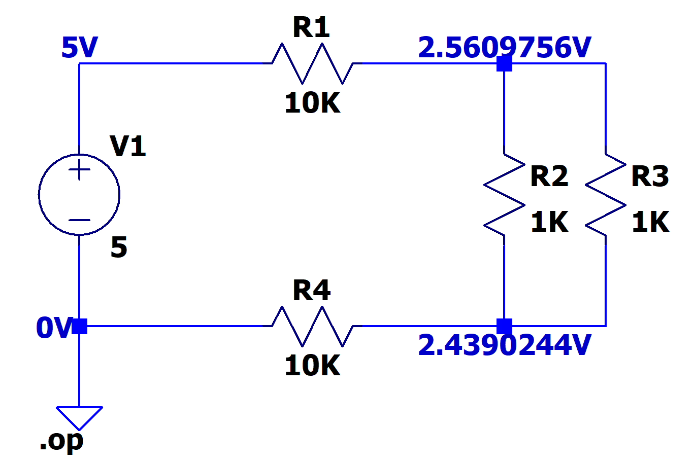
Proof of Concept - Omega Lab 01 - 1 - Simulation
 1
 2
 3
 4
 5
 6
 7
 8
 9
10
       --- Operating Point ---

V(n001):     5     voltage
V(n002):     2.56098     voltage
V(n003):     2.43902     voltage
I(R1):     -0.000243902     device_current
I(R2):     0.000121951     device_current
I(R3):     0.000121951     device_current
I(R4):     0.000243902     device_current
I(V1):     -0.000243902     device_current
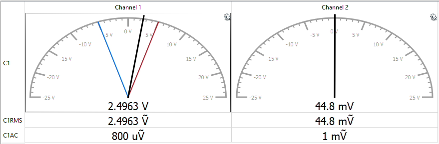
We can see that V(R1) and V(R4) are very accurate. But V(R2) and V(R3) has a lot of error. A potential explanation is that, there is a background noise.
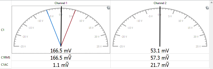
If we look at the “Measurement”, channel 2 is empty, but it still has a reading around 50mV. It’s very likely to be a background noise. If we remove this noise from Experimental Measurements. The %diff will be less than 1%. Consider that the resistor has a Tolerance of 5% (from 4 Band Resistor Color Code). We can consider this as systematic error and the Experimental Measurements is very close to Simulations.
Then, we can check these current result with simulation data.
Items
Analysis
Simulation
Experiment
diff
%diff
I(R1)
0.2439mA
0.2439mA
0.2496mA
0.005728mA
2.3%
I(R2)
0.1665mA
0.1665mA
0.1219mA
0.044549mA
26.8%
I(R3)
0.1665mA
0.1665mA
0.1219mA
0.044549mA
26.8%
I(R4)
0.2439mA
0.2439mA
0.2461mA
0.002258mA
0.9%
We can see that I(R1) and I(R4) are very accurate. But I(R2) and I(R3) has a lot of error. A potential explanation is that, there is a background noise.
If we look at the “Measurement”, channel 2 is empty, but it still has a reading around 50mV. It’s very likely to be a background noise. If we remove this noise from Experimental Measurements. The %diff will be less than 1%. Consider that the resistor has a Tolerance of 5% (from 4 Band Resistor Color Code). We can consider this as systematic error and the Experimental Measurements is very close to Simulations.
Also, we can check to total current in the circuit. Using the expectation form “Analysis” - Itotal=0.000243902439, this matches the simulation - 0.000243902A.
In conclusion, the simulation 100% fit the KCL and KVL. The experimental data is close to the simulation. And very close to simulation if we remove the background noise and consider the 5% tolerance of the resistor. Then, we used Ohm’s Law with experimental data to compare the simulation. The result is also very close. Thus, we proved Ohm’s Law, KCL, and KVL in a Circuit.
2. Prove the Concept of a Voltage Divider in a Series Circuit
Circuit Schematic
Proof of Concept - Omega Lab 01 - 2 - Schematic
Description
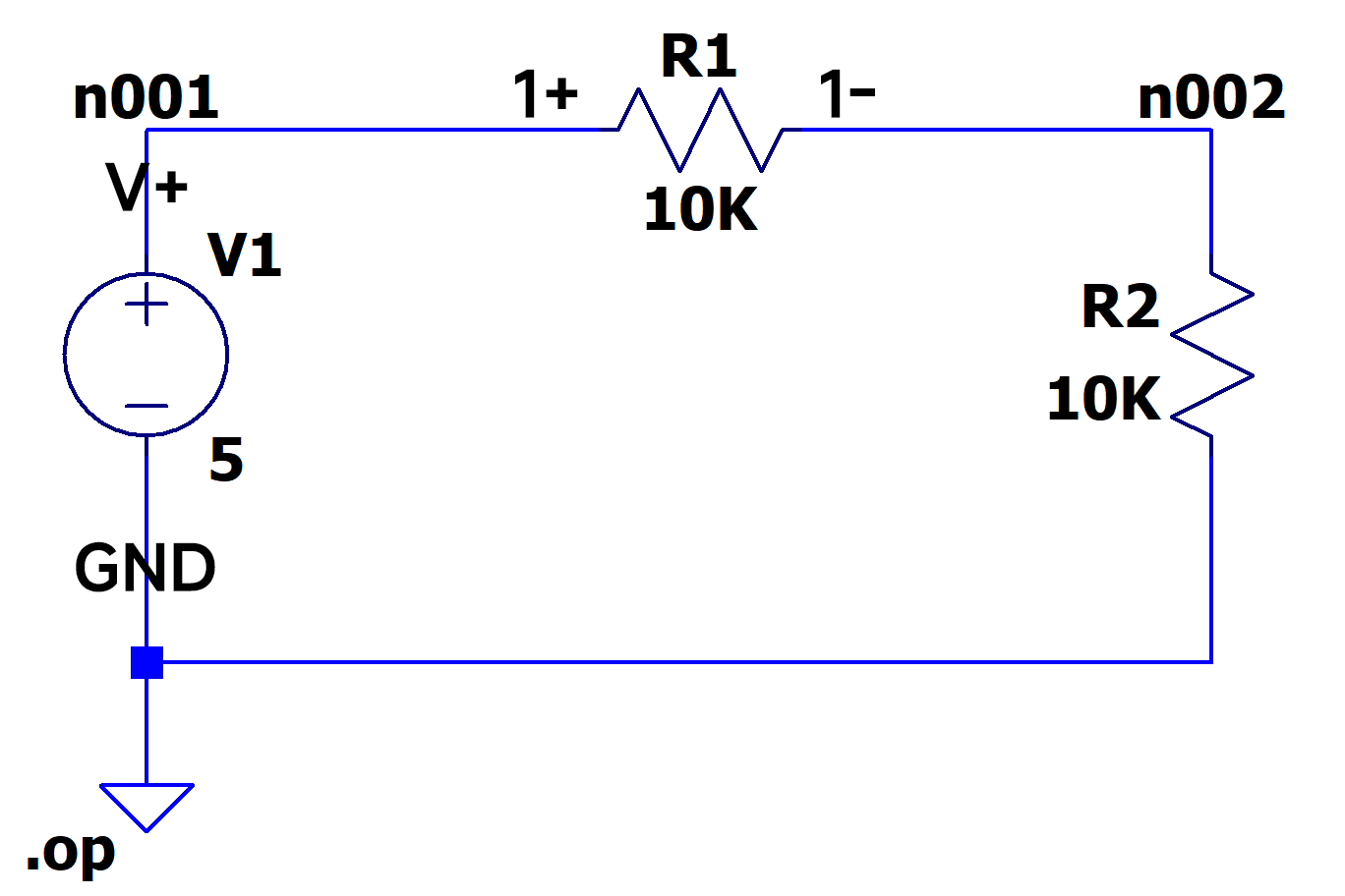
I am going to build a series circuit with two resistors and measure the voltage across the resistors to compare the theoretic values.
Analysis
The Voltage Divider equation is
V2V1=R2R1
If we have the voltage source 5V and R1=R2=10K. Put the values into the equation and get
V2V1=10K10K=11
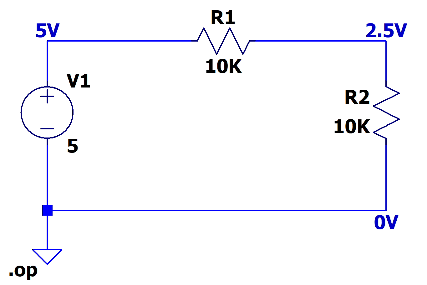
We know that V1+V2=5 and 1⋅V1=1⋅V2. So, we should expect V1=V2=2.5.
Simulation
Proof of Concept - Omega Lab 01 - 2 - Simulation
1
2
3
4
5
6
7
       --- Operating Point ---

V(n001):     5     voltage
V(n002):     2.5     voltage
I(R1):     -0.00025     device_current
I(R2):     -0.00025     device_current
I(V1):     -0.00025     device_current
We can see that both V(R1) and V(R2) are very accurate. They are some errors, A potential explanation is that, there is a background noise.
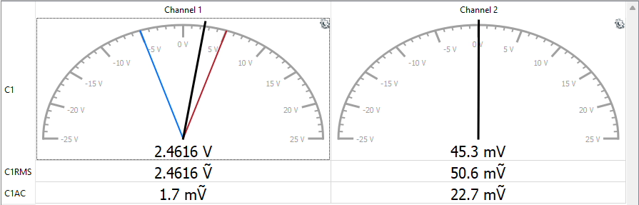
If we look at the “Measurement”, channel 2 is empty, but it still has a reading around 40mV. It’s very likely to be a background noise. If we remove this noise from Experimental Measurements. The %diff will be less than 1%. Consider that the resistor has a Tolerance of 5% (from 4 Band Resistor Color Code). We can consider this as systematic error and the Experimental Measurements is very close to Simulations.
In conclusion, the simulation 100% fits the Voltage Divider theoretic formula. And the experimental reading is close to theoretic values. And the experimental reading is very close to theoretic values if we removed the background noise. Thus, we proved the Concept of a Voltage Divider in a Series Circuit.
3. Prove the Concept of How Current Flows in a Series Circuit
Circuit Schematic
Proof of Concept - Omega Lab 01 - 2 - Schematic
Description
I am going to use the Ohm’s Law to find out the current flows through every resistor in the series circuit and compare it with the theoretic values.
Analysis
The feature of series circuit is that
There is only one path for the current to flow through the circuit.
The current is the same at any point in the circuit.
Since Analog Discovery 3 can’t directly measures the current but the voltage. We are going to use Ohm’s Law to find out the current flow through the resistor.
We know this relationship from Ohm’s Law
V=IR
We can change it a bit into
I=RV
Also, we know that R1=R2=10K and the voltage across the resistor can be found by voltage divider formula. which is
V2V1V2V1=R2R1=10K10K=11
We know that V1+V2=5 and 1⋅V1=1⋅V2. So, we should expect V1=V2=2.5.
Using these values, we can find out I(R1) and I(R2) by
Both R1 and R2 are very close, we can say that R1≈R2. Consider that the resistor has a Tolerance of 5% (from 4 Band Resistor Color Code). We can consider this as systematic error and the Experimental Measurements is very close to Simulations.
In conclusion, the simulation 100% fits the feature of current in series circuit. And the experimental reading is close to theoretic values. And the experimental reading is very close to theoretic values if we consider that the resistor has a Tolerance of 5% (from 4 Band Resistor Color Code). Thus, we proved the Concept of How Current Flows in a Series Circuit.
There is only one path for the current to flow through the circuit.
The current is the same at any point in the circuit.
4. Prove the Concept of Voltage Across a Parallel Circuit
Circuit Schematic
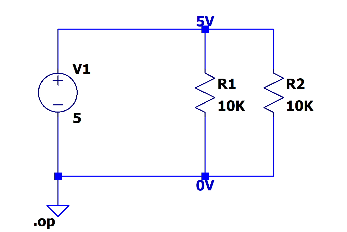
Proof of Concept - Omega Lab 01 - 4 - Schematic
Description
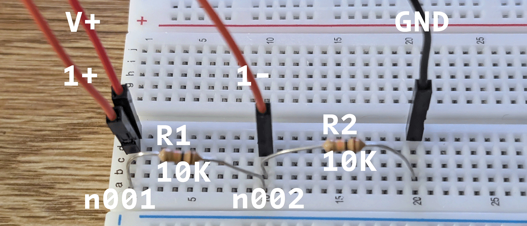
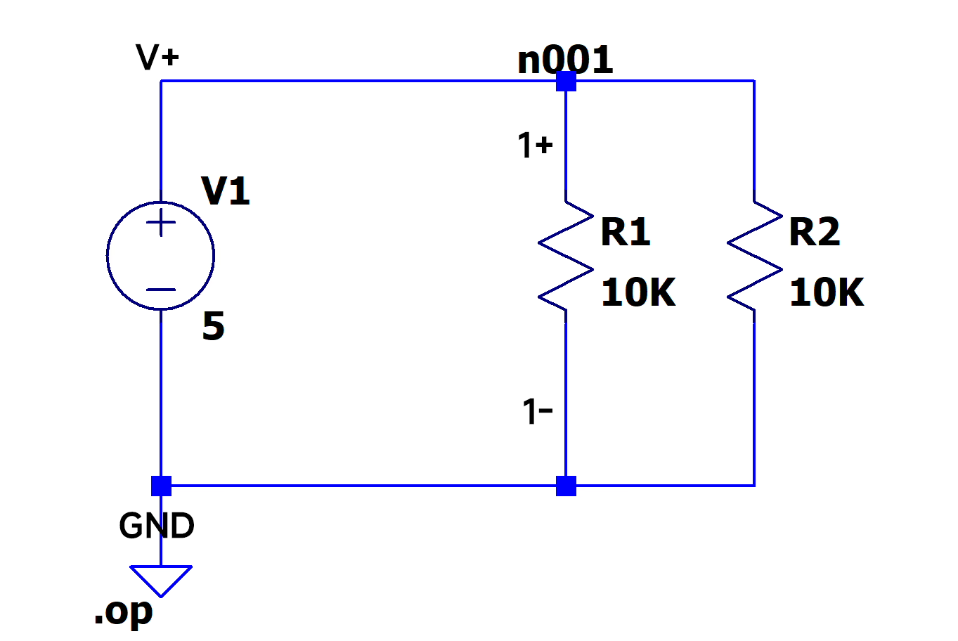
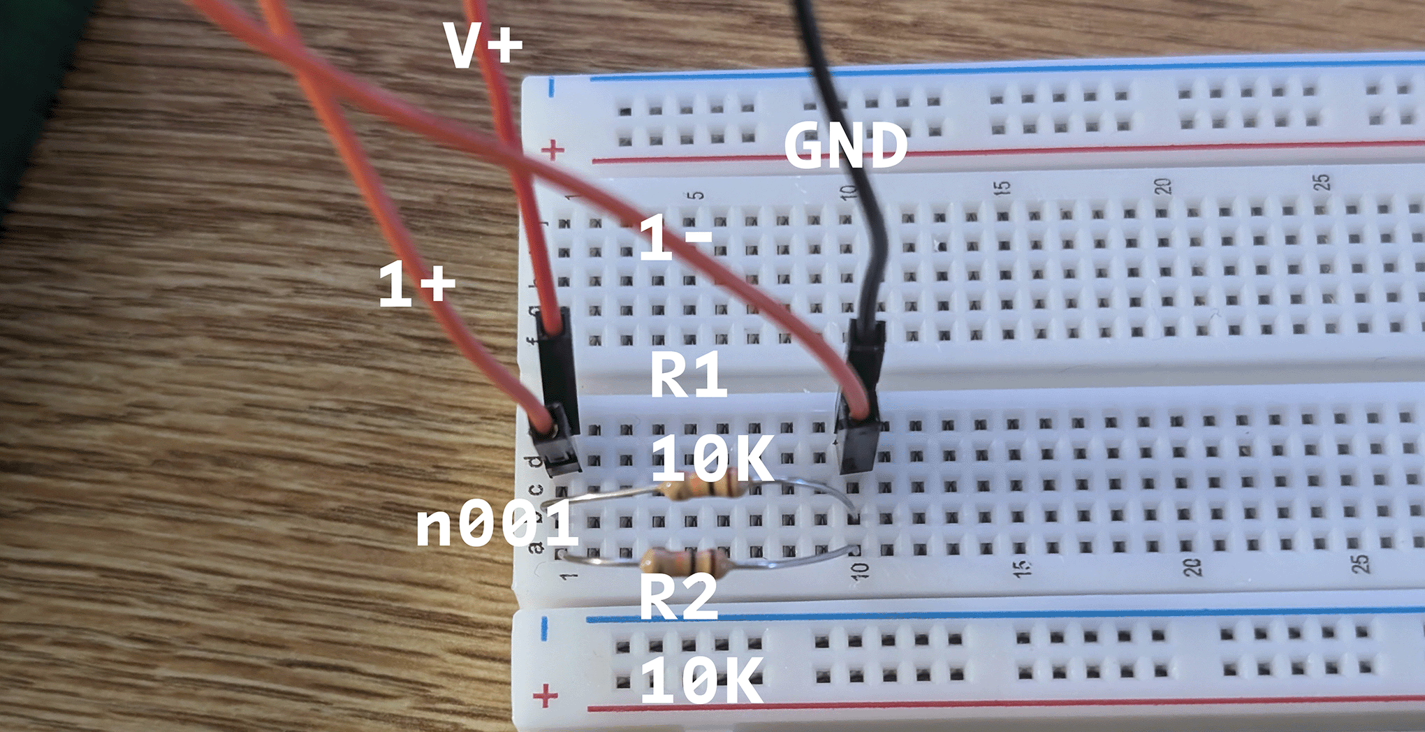
I am going to use the Ohm’s Law and feature of node to find out the voltage across every resistor in the parallel circuit and compare it with the theoretic values.
Analysis
The feature of parallel circuit is that
There are multiple paths for the current to flow through the circuit.
The voltage across each branch is the same and equal to the voltage supplied by the source.
Vtotal=V1=V2=V3=…=Vn
We know that the voltage in the same node is the same (they are connected by a wire). And n001, n002 connected both side of resistor. So, we should expect V(R1)=V(R2).
Also, the voltage is potential difference between the component.
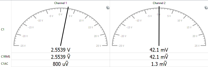
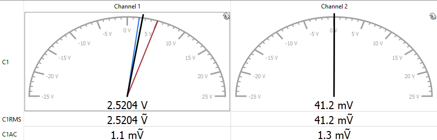
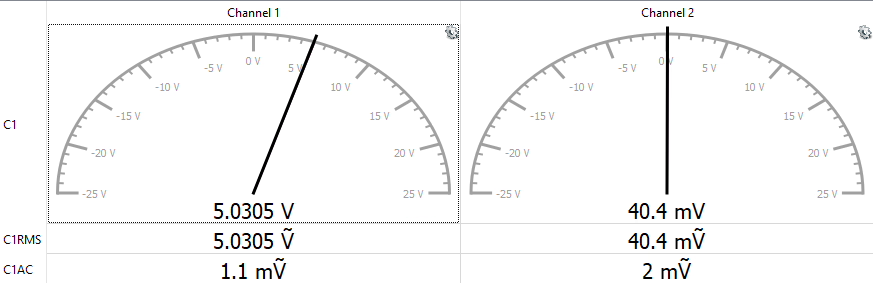
We can see that both V(R1) and V(R2) are very accurate. They are some errors, A potential explanation is that, there is a background noise.
If we look at the “Measurement”, channel 2 is empty, but it still has a reading around 40mV. It’s very likely to be a background noise. If we remove this noise from Experimental Measurements. The %diff will be less than 0.2%. Consider that the resistor has a Tolerance of 5% (from 4 Band Resistor Color Code). We can consider this as systematic error and the Experimental Measurements is very close to Simulations.
Secondly, we can check to Itotal as double confirm.
Additionally, we can check the experimental data as well. Since Analog Discovery 3 can’t measure the current directly, we need use Ohm’s Law to find out current.
0.0005305≈0.0005 with only 0.6%diff (even less then 0.2% if we remove 40mV background noise). Our theory is very likely be true. Since the resistor has a Tolerance of 5% (from 4 Band Resistor Color Code). We can consider this as systematic error and the Experimental Measurements is very close to Simulations.
In conclusion, we checked the simulation 100% fit the Analysis’ expectation. And the experimental data only has 0.2% to 0.6% than the theoretic values. Thus, we proved Concept of Voltage Across a Parallel Circuit.
There are multiple paths for the current to flow through the circuit.
The voltage across each branch is the same and equal to the voltage supplied by the source.
5. Prove the Concept of a Current Divider in a Parallel Circuit
Circuit Schematic
Proof of Concept - Omega Lab 01 - 4 - Schematic
Description
I am going to use the Ohm’s Law to find out the current across every resistor in the parallel circuit and compare its sum with the theoretic values.
Analysis
The feature of parallel circuit is that
There are multiple paths for the current to flow through the circuit.
The voltage across each branch is the same and equal to the voltage supplied by the source.
The total current entering the parallel circuit is divided among the branches.
Vtotal=V1=V2=V3=…=Vn
We know that the voltage in the same node is the same (they are connected by a wire). And n001, n002 connected both side of resistor. So, we should expect V(R1)=V(R2).
Also, the voltage is potential difference between the component.
We can see that both V(R1) and V(R2) are very accurate. They are some errors, A potential explanation is that, there is a background noise.
If we look at the “Measurement”, channel 2 is empty, but it still has a reading around 40mV. It’s very likely to be a background noise. If we remove this noise from Experimental Measurements. The %diff will be less than 0.2%. Consider that the resistor has a Tolerance of 5% (from 4 Band Resistor Color Code). We can consider this as systematic error and the Experimental Measurements is very close to Simulations.
Second, let’s check I(R1) and I(R2) with theoretical values.
Since Analog Discovery 3 can’t measure the current directly, we need use Ohm’s Law to find out current.
We can see that both I(R1) and I(R2) are very accurate. They are some errors, A potential explanation is that, there is a background noise.
If we look at the “Measurement”, channel 2 is empty, but it still has a reading around 40mV. It’s very likely to be a background noise. If we remove this noise from Experimental Measurements. The %diff will be less than 0.2%. Consider that the resistor has a Tolerance of 5% (from 4 Band Resistor Color Code). We can consider this as systematic error and the Experimental Measurements is very close to Simulations.
In conclusion, we checked the simulation 100% fit the Analysis’ expectation. And the experimental data only has 0.2% to 0.6% than the theoretic values. Thus, we proved Concept of How Current Flows in a Series Circuit.
There are multiple paths for the current to flow through the circuit.
The voltage across each branch is the same and equal to the voltage supplied by the source.
The total current entering the parallel circuit is divided among the branches.
6. Prove the Concept of a Voltage Divider in Temperature Sensing Circuit
Circuit Schematic
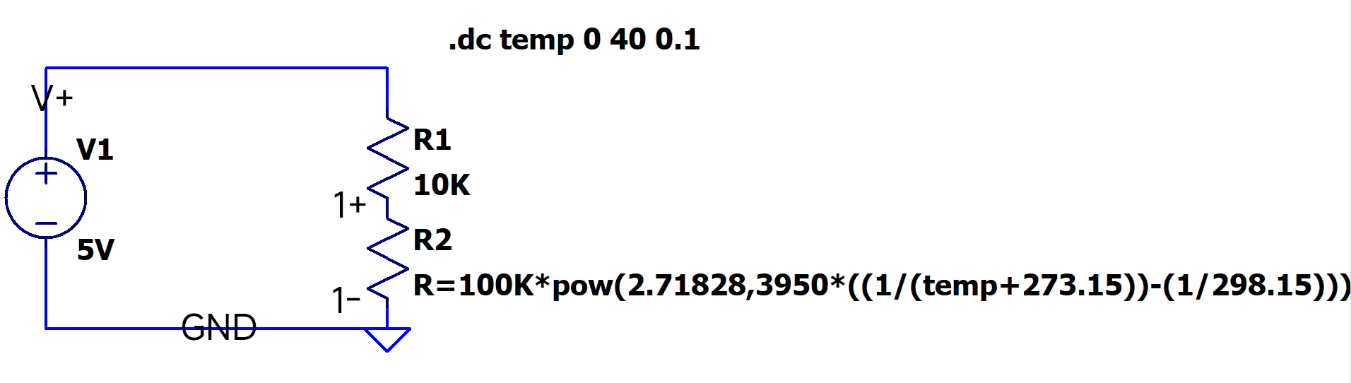
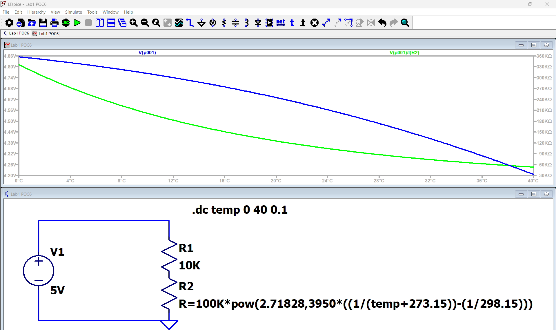
Proof of Concept - Omega Lab 01 - 6 - Schematic
Description
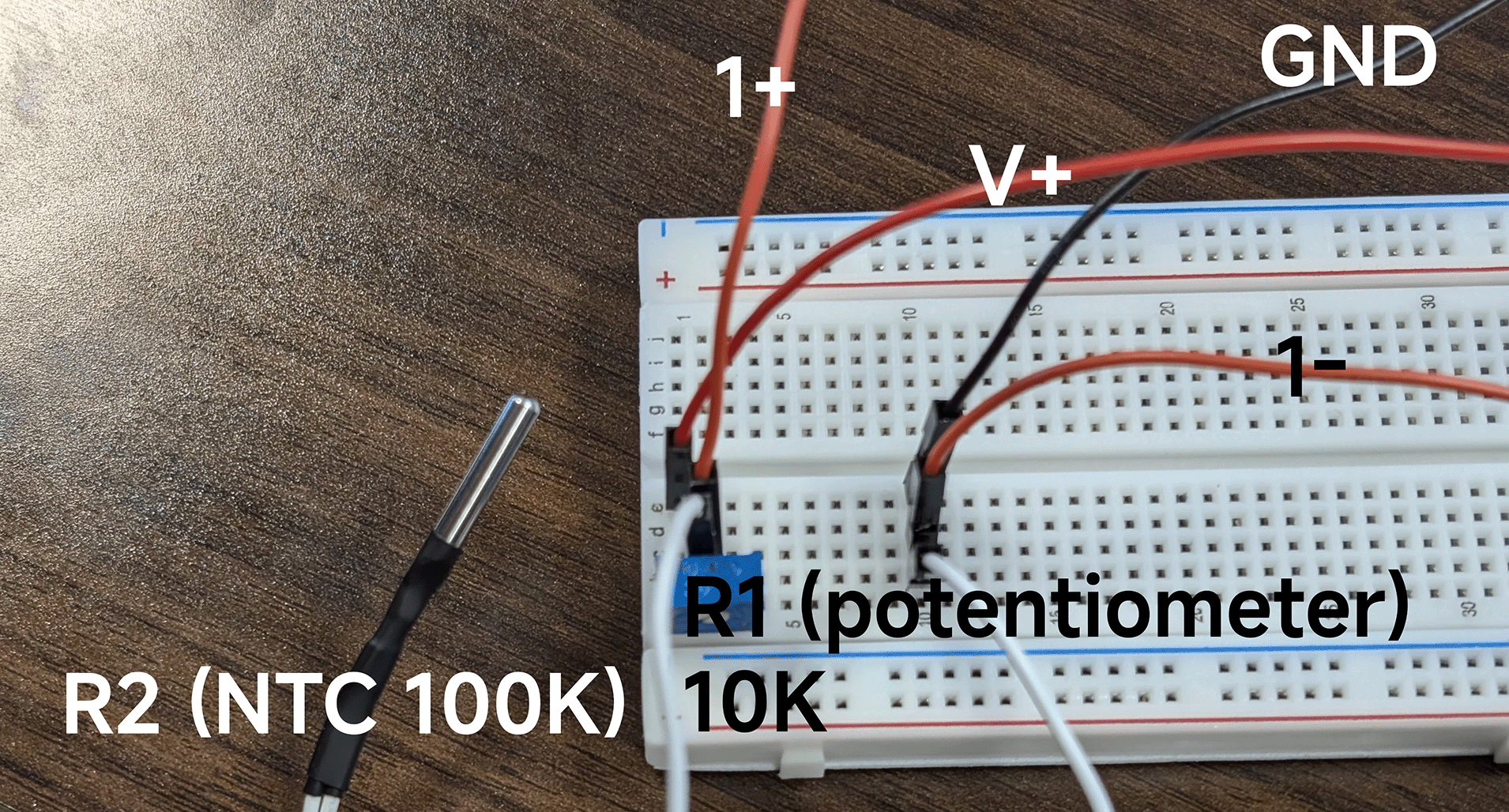
We are going to use NTC 100K as our thermistor, and we will compare the reading with our thermometer and simulation to check its reliability.
Analysis
NTC thermistor uses Beta formula to calculate the resistance under a specific temperature. The formula is like
T11=T01+β1ln(R0R1)
We can move R1 to the left side to get
R1=R0eβ(T1−1−T0−1)
Since we want to find out the resistance of this thermistor under a specific temperature.
The thermistor we are using is NTC 100K. Which means it has 100kΩ at the reference temperature 25°C
T0=298.15KR0=100kΩ
Also, we got the β value from the manufacturer, which
β=3950
We know the Voltage Divider
V2V1=R2R1
put them together, we got
V2V1=R2R0eβ(T1−1−T0−1)
Simulation
Proof of Concept - Omega Lab 01 - 6 - Simulation
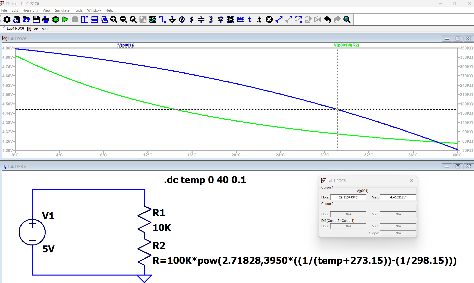
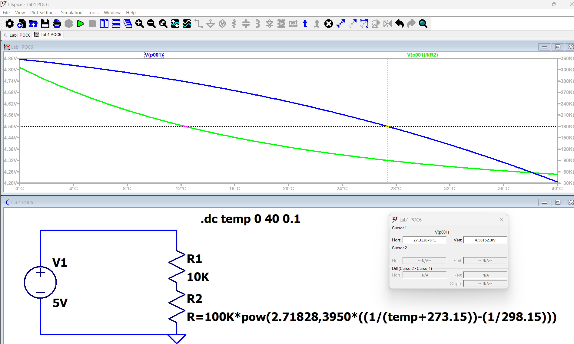
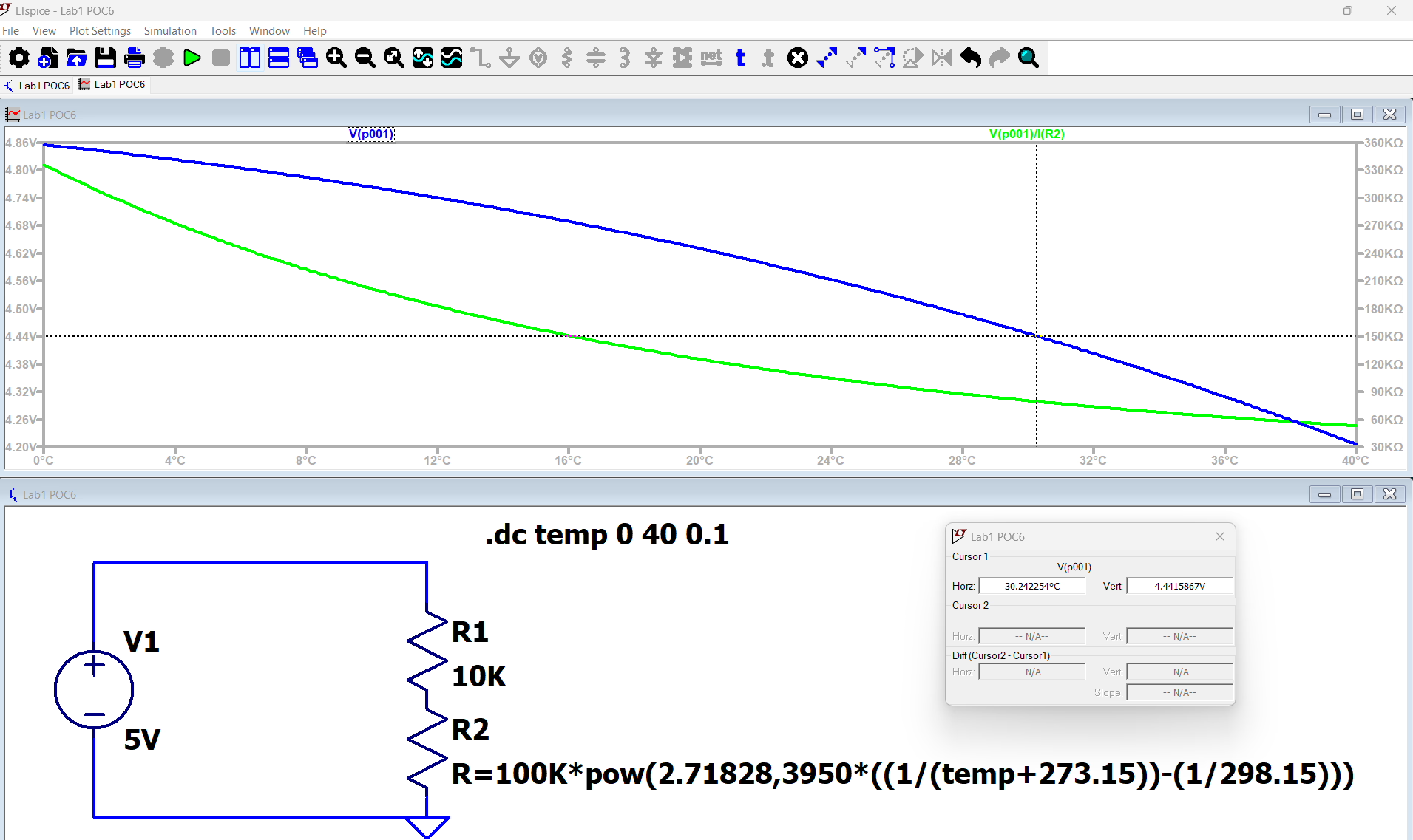
We got a curve shows the relationship between the temperature and resistance in range of T=0°C to T=40°C
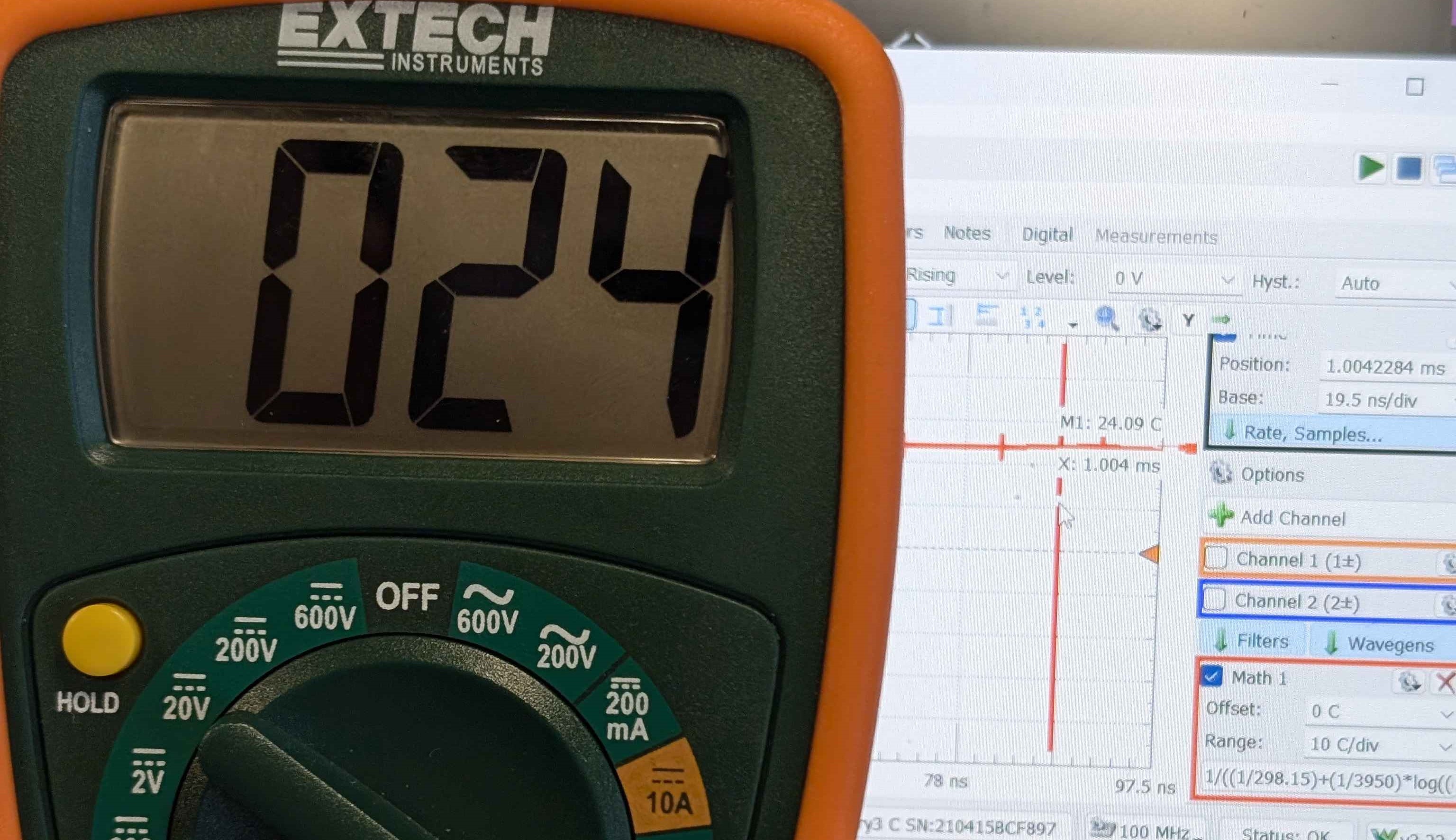
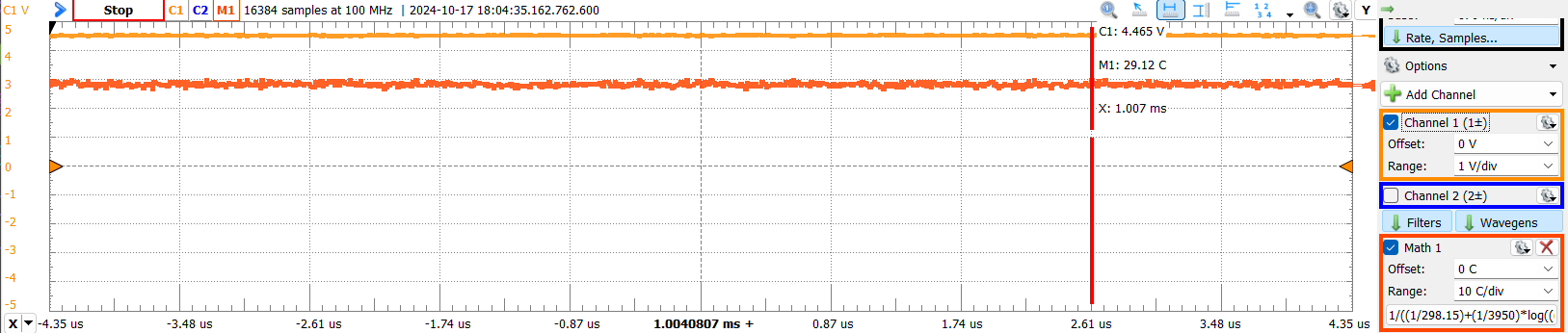
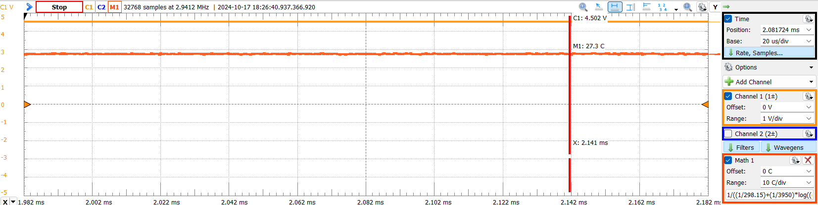
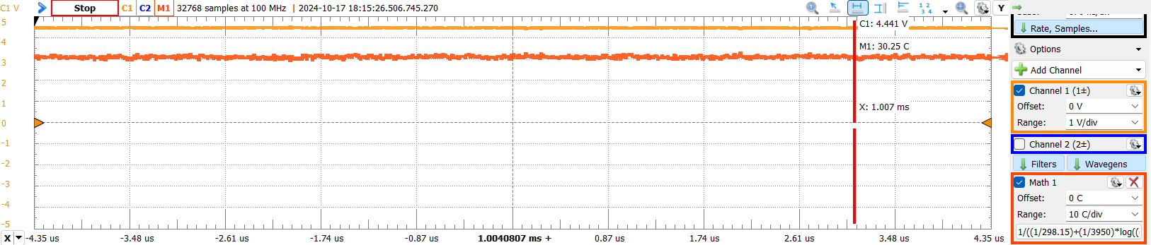
As we can see, the difference between theory and measurements is extremely small. This may due to the temperature reading is calculated from voltage by Math.
But even we look the thermometer’s reading, both of them shows around 24°C. In the worst case, the error is 5%. So, over all, our reading is reliable.
The wheatstone bridge is better than a normal voltage divider because it is more sensitive than a voltage divider. A voltage divider relies on the ratio of resistances between two resistors, so even if the ratio of the resistors change, as long as the change isn’t massive, the output voltage stays the same.
When a wheatstone bridge is balanced, meaning R1/R2=R3/R4, the current flowing through the galvanometer in the center of the wheatstone bridge is 0. When current is zero, the calculated resistance is no longer affected by innate resistance of wires, resistors, and voltameters. This allows measurements with the wheatstone bridge to be more accurate than a voltage divider.
Advantages:
Wheatstone bridge is more accurate than voltage divider
Voltage source does not need to be calibrated to measure resistance
 James included in Electrical Engineering and ECSE 1010